David-H-Gesture-Controlled-Car
This is my project page for the Gesture Controlled Car that I built.
Project maintained by DHSIAO05 Hosted on GitHub Pages — Theme by mattgraham
Gesture Controlled Car with Accelerometer
I am working on a gesture controlled car using arduino with an esp32 chip
| Engineer | School | Area of Interest | Grade |
|---|---|---|---|
| David Hsiao | Leland High School | Computer Engineer | Incoming Senior |

Demo Night
This is my Demo Night Presentation where I talked about the modifications I added to my car. I specifically talked about the ultrasonic sensor and the science behind it and continued talking about how it is used in my car. I showed a demo of the sensor working and later showed the LED I installed and how it was used. I then talk about my favorite and hardest part of the whole project and asked the audience for any questions.
Reflection
Overall, I had a really fun experience at my time with Bluestamp. I looked foward for every class because I kept wanting to complete the robot and just add as much as I can onto it. I will definitely add more modifications in the future and this camp made my interest for engineering and coding increase by a lot.
Final Milestone
My final milestone was to add the specific movements to my car. So when I move my accelerometer to a specific direction my car would move that direction. For moving forward and backward, it was pretty easy to code, but when I coded for it to turn left or right, I had a little confusion. I realized if I wanted my car to turn left, I would make the two left wheels move forward and the two right wheels move backward or vice versa when I wanted it to turn right. After I coded everything, I tested my car, if the wheels would move and at first, it did move, but at a really slow pace. I figured out that my dutyCycle in my arduino was at 200, so I changed it to 255 which is the max. I uploaded and tested it after and my car moved smoothly. I was pretty much done with my base project and I just needed to tape everything on such as my ESP32, L298N Motor Driver, and the battery pack. I wanted to add modifications to my car, so I added an ultrasonic sensor. How it works is that the sensor emits sound waves, and then it waits for the sound to be reflected back, which calculates the distance based on the time required. This is to prevent my car from hitting a wall. I found a code where the serial monitor will print out the distance from the sensor to an object or wall. At first, when I checked the serial monitor, the sensor wouldn’t get a read. I realized that the voltage input was at 3.3 instead of 5. I changed it to 5, and I successfully got a read. I then coded my forward movement so that, when the sensor is at a certain distance from an object, the forward motion would stop working and I could only turn right, left, or backwards. I also added an LED so whenever my car is stopped, the LED will light up.
Ultrasonic Sensor

Ultrasonic Sensor Code
// defines pins numbers
const int trigPin = 16;
const int echoPin = 17;
// defines variables
long duration;
int distance;
void setup() {
pinMode(trigPin, OUTPUT); // Sets the trigPin as an Output
pinMode(echoPin, INPUT); // Sets the echoPin as an Input
Serial.begin(9600); // Starts the serial communication
}
void loop() {
// Clears the trigPin
digitalWrite(trigPin, LOW);
delayMicroseconds(2);
// Sets the trigPin on HIGH state for 10 micro seconds
digitalWrite(trigPin, HIGH);
delayMicroseconds(10);
digitalWrite(trigPin, LOW);
// Reads the echoPin, returns the sound wave travel time in microseconds
duration = pulseIn(echoPin, HIGH);
// Calculating the distance
distance= duration*0.034/2;
// Prints the distance on the Serial Monitor
Serial.print("Distance: ");
Serial.println(distance);
}
Car Movement Code
 if (message == "Forwar") {
      if (distance > 10) {
        int dutyCycle = 255;
        digitalWrite(motor1Pin1, LOW);
        digitalWrite(motor1Pin2, HIGH);
        digitalWrite(motor2Pin1, LOW);
        digitalWrite(motor2Pin2, HIGH);
        ledcWrite(pwmChannel, dutyCycle);
      }
      else {
        digitalWrite(motor1Pin1, LOW);
        digitalWrite(motor1Pin2, LOW);
        digitalWrite(motor2Pin1, LOW);
        digitalWrite(motor2Pin2, LOW);
      }
    }
    else if (message == "Backwar") {
      int dutyCycle = 255;
      digitalWrite(motor1Pin1, HIGH);
      digitalWrite(motor1Pin2, LOW);
      digitalWrite(motor2Pin1, HIGH);
      digitalWrite(motor2Pin2, LOW);
      ledcWrite(pwmChannel, dutyCycle);
    }
    else if (message == "Lef") {
      int dutyCycle = 255;
      digitalWrite(motor1Pin1, HIGH);
      digitalWrite(motor1Pin2, LOW);
      digitalWrite(motor2Pin1, LOW);
      digitalWrite(motor2Pin2, HIGH);
      ledcWrite(pwmChannel, dutyCycle);
    }
    else if (message == "Righ") {
      int dutyCycle = 255;
      digitalWrite(motor1Pin1, LOW);
      digitalWrite(motor1Pin2, HIGH);
      digitalWrite(motor2Pin1, HIGH);
      digitalWrite(motor2Pin2, LOW);
      ledcWrite(pwmChannel, dutyCycle);
    }
    else if (message == "Stoppe") {
      digitalWrite(motor1Pin1, LOW);
      digitalWrite(motor1Pin2, LOW);
      digitalWrite(motor2Pin1, LOW);
      digitalWrite(motor2Pin2, LOW);
    }
    else {
      Serial.println("error");
    }
Second Milestone
My second milestone was understanding the accelerometer. I first had to learn how to solder, so I could connect my ESP32 to the accelerometer. Through arduino, I put in a code which shows the acceleration, roatation, and the temperature of the accelerometer. I ran many trials through the accelerometer by tilting it around, seeing which coordinates on the rotations would go up or down if I tilt it in a specific way. Once I figured that out, I wrote a code where when the accelerometer tilts a certain direction, it prints out that corresponding direction. After that, I put in a code through arduino which shows the angle of the accelerometer, which would give it a more specific read. I did the same thing where I ran many trials to see which numbers would go up or down, when the accelerometer is tilted. It printed out with more accurate reads and results compared to the rotations. This is to move the robot, so for example, if I tilt forward with my hand, the robot would move forward. The accelerometer would control the robots movements. After that, I needed to sync my two ESP32 chips so that one would send a signal and one would receive that signal. I first needed to find the MAC addresses for the two ESP32 so they would get a signal to each other. Then, I knew that the accelerometer would be the one sending the signals, and my car would be receiving it.
ESP32 to Accelerometer Schematics

Accelerometer Code
#include<Wire.h>
#include<TwoWayESP.h>
const uint8_t otherESPAddr[6] = {0x08, 0x3A, 0xF2, 0x6C, 0xFE, 0xE8 };

const int MPU_addr = 0x68;
int16_t AcX, AcY, AcZ, Tmp, GyX, GyY, GyZ;

int minVal = 265;
int maxVal = 402;

double x;
double y;
double z;

void setup() {
  TwoWayESP::Begin(otherESPAddr);
  Wire.begin();
  Wire.beginTransmission(MPU_addr);
  Wire.write(0x6B);
  Wire.write(0);
  Wire.endTransmission(true);
  Serial.begin(115200);
}
void loop() {
  Wire.beginTransmission(MPU_addr);
  Wire.write(0x3B);
  Wire.endTransmission(false);
  Wire.requestFrom(MPU_addr, 14, true);
  AcX = Wire.read() << 8 | Wire.read();
  AcY = Wire.read() << 8 | Wire.read();
  AcZ = Wire.read() << 8 | Wire.read();
  int xAng = map(AcX, minVal, maxVal, -90, 90);
  int yAng = map(AcY, minVal, maxVal, -90, 90);
  int zAng = map(AcZ, minVal, maxVal, -90, 90);

  x = RAD_TO_DEG * (atan2(-yAng, -zAng) + PI);
  y = RAD_TO_DEG * (atan2(-xAng, -zAng) + PI);
  z = RAD_TO_DEG * (atan2(-yAng, -xAng) + PI);

  Serial.print("AngleX= ");
  Serial.println(x);

  Serial.print("AngleY= ");
  Serial.println(y);

  Serial.print("AngleZ= ");
  Serial.println(z);
  Serial.println("-----------------------------------------");
  delay(10);

  String send;
  if (x >= 40 && x <= 100) {
    send = "Forward";
    Serial.println(send);
  }
  else if (x <= 310 && x >= 260) {
    send = "Backward";
    Serial.println(send);
  }

  else if (y >= 100 && y <= 200) {
    send = "Right";
    Serial.println(send);
  }
  else if (y <= 65 && y >= 0) {
    send = "Left";
    Serial.println(send);
  }
  else {
    send = "Stopped";
    Serial.println(send);
  }
 TwoWayESP::SendString(send);
}
Receiver Code
#include <TwoWayESP.h>

int motor1Pin1 = 27;
int motor1Pin2 = 26;
int enable1Pin = 14;
int motor2Pin1 = 32;
int motor2Pin2 = 33;
int enable2Pin = 25;

// Setting PWM properties
const int freq = 30000;
const int pwmChannel = 0;
const int resolution = 8;
int dutyCycle = 255;

// defines pins numbers
const int trigPin = 16;
const int echoPin = 17;
// defines variables
long duration;
int distance;

// Make this the OTHER ESPs mac address
// The mac address can be found by uploading this program
// It will be output on the serial terminal
const uint8_t otherESPAddr[6] = {0x08, 0x3A, 0xF2, 0x6D, 0x07, 0xEC };

void setup() {
  // sets the pins as outputs:
  pinMode(motor1Pin1, OUTPUT);
  pinMode(motor1Pin2, OUTPUT);
  pinMode(enable1Pin, OUTPUT);
  pinMode(motor2Pin1, OUTPUT);
  pinMode(motor2Pin2, OUTPUT);
  pinMode(enable2Pin, OUTPUT);

  // configure LED PWM functionalitites
  ledcSetup(pwmChannel, freq, resolution);

  // attach the channel to the GPIO to be controlled
  ledcAttachPin(enable1Pin, pwmChannel);
  ledcAttachPin(enable2Pin, pwmChannel);

  pinMode(trigPin, OUTPUT); // Sets the trigPin as an Output
  pinMode(echoPin, INPUT); // Sets the echoPin as an Input

  Serial.begin(115200);

  // Begin TwoWayESP with the other ESPs mac
  TwoWayESP::Begin(otherESPAddr);
}

void loop() {
  // Clears the trigPin
  digitalWrite(trigPin, LOW);
  delayMicroseconds(2);
  // Sets the trigPin on HIGH state for 10 micro seconds
  digitalWrite(trigPin, HIGH);
  delayMicroseconds(10);
  digitalWrite(trigPin, LOW);
  // Reads the echoPin, returns the sound wave travel time in microseconds
  duration = pulseIn(echoPin, HIGH);
  // Calculating the distance
  distance = duration * 0.034 / 2;
  // Prints the distance on the Serial Monitor
  Serial.print("Distance: ");
  Serial.println(distance);
  // Check if there is an available read
  if (TwoWayESP::Available()) {
    //Serial.print("[Incoming] String data: ");
    //Serial.println(TwoWayESP::GetString());
    String message = TwoWayESP::GetString();
    Serial.println(message);
    if (message == "Forwar") {
      if (distance > 10) {
        int dutyCycle = 255;
        digitalWrite(motor1Pin1, LOW);
        digitalWrite(motor1Pin2, HIGH);
        digitalWrite(motor2Pin1, LOW);
        digitalWrite(motor2Pin2, HIGH);
        ledcWrite(pwmChannel, dutyCycle);
      }
      else {
        digitalWrite(motor1Pin1, LOW);
        digitalWrite(motor1Pin2, LOW);
        digitalWrite(motor2Pin1, LOW);
        digitalWrite(motor2Pin2, LOW);
      }
    }
    else if (message == "Backwar") {
      int dutyCycle = 255;
      digitalWrite(motor1Pin1, HIGH);
      digitalWrite(motor1Pin2, LOW);
      digitalWrite(motor2Pin1, HIGH);
      digitalWrite(motor2Pin2, LOW);
      ledcWrite(pwmChannel, dutyCycle);
    }
    else if (message == "Lef") {
      int dutyCycle = 255;
      digitalWrite(motor1Pin1, HIGH);
      digitalWrite(motor1Pin2, LOW);
      digitalWrite(motor2Pin1, LOW);
      digitalWrite(motor2Pin2, HIGH);
      ledcWrite(pwmChannel, dutyCycle);
    }
    else if (message == "Righ") {
      int dutyCycle = 255;
      digitalWrite(motor1Pin1, LOW);
      digitalWrite(motor1Pin2, HIGH);
      digitalWrite(motor2Pin1, HIGH);
      digitalWrite(motor2Pin2, LOW);
      ledcWrite(pwmChannel, dutyCycle);
    }
    else if (message == "Stoppe") {
      digitalWrite(motor1Pin1, LOW);
      digitalWrite(motor1Pin2, LOW);
      digitalWrite(motor2Pin1, LOW);
      digitalWrite(motor2Pin2, LOW);
    }
    else {
      Serial.println("error");
    }
  }
}
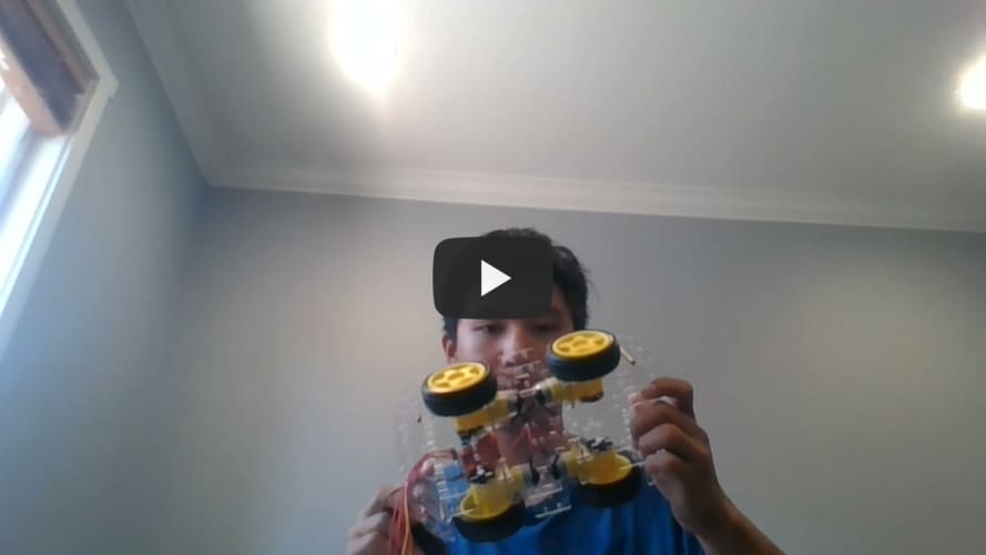
First Milestone
My first milestone was building the car chassis and getting all of my motors to work. I first started off building the car chassis, so screwing in the DC motors in and putting the rubber wheels. I needed to understand all of the components that were used such as the ESP32, L298N Motor Driver, and where all of the wirings should go. I first started with trying to get the two left wheels to work by plugging all of the wires from the ESP32 to the motor driver. I then connected the wires from the motors to the motor drivers and plugged a battery pack to the driver to power it. The L298N Motor Driver is perfect for this because it can handle up to 3A at 35V and allows us to drive four DC motors simultaneously. After, I checked my arduino code, making sure all of the inputs were correct so that the wheels would spin. I then did the same thing for the two right wheels and at first they spun the opposite direction from the two left wheels. I noticed that I had plugged in the wires incorrectly, but I managed to fix it. Finally, I put in the code for the two right wheels, making sure that I had all of my inputs correct corresponding to its wheels, and they all spun in sync.
ESP32 to L298N Motor Driver Schematics

Motor Test Code
// Motor A
int motor1Pin1 = 27;
int motor1Pin2 = 26;
int enable1Pin = 14;
int motor2Pin1 = 32;
int motor2Pin2 = 33;
int enable2Pin = 25;

// Setting PWM properties
const int freq = 30000;
const int pwmChannel = 0;
const int resolution = 8;
int dutyCycle = 200;

void setup() {
  // sets the pins as outputs:
  pinMode(motor1Pin1, OUTPUT);
  pinMode(motor1Pin2, OUTPUT);
  pinMode(enable1Pin, OUTPUT);
  pinMode(motor2Pin1, OUTPUT);
  pinMode(motor2Pin2, OUTPUT);
  pinMode(enable2Pin, OUTPUT);

  // configure LED PWM functionalitites
  ledcSetup(pwmChannel, freq, resolution);

  // attach the channel to the GPIO to be controlled
  ledcAttachPin(enable1Pin, pwmChannel);
  ledcAttachPin(enable2Pin, pwmChannel);

  Serial.begin(115200);

  // testing
  Serial.print("Testing DC Motor...");
}

void loop() {
  // Move the DC motor forward at maximum speed
  Serial.println("Moving Forward");
  digitalWrite(motor1Pin1, LOW);
  digitalWrite(motor1Pin2, HIGH);
  digitalWrite(motor2Pin1, LOW);
  digitalWrite(motor2Pin2, HIGH);
  delay(2000);

  // Stop the DC motor
  Serial.println("Motor stopped");
  digitalWrite(motor1Pin1, LOW);
  digitalWrite(motor1Pin2, LOW);
  digitalWrite(motor2Pin1, LOW);
  digitalWrite(motor2Pin2, LOW);
  delay(1000);

  // Move DC motor backwards at maximum speed
  Serial.println("Moving Backwards");
  digitalWrite(motor1Pin1, HIGH);
  digitalWrite(motor1Pin2, LOW);
  digitalWrite(motor2Pin1, HIGH);
  digitalWrite(motor2Pin2, LOW);
  delay(2000);

  // Stop the DC motor
  Serial.println("Motor stopped");
  digitalWrite(motor1Pin1, LOW);
  digitalWrite(motor1Pin2, LOW);
  digitalWrite(motor2Pin1, LOW);
  digitalWrite(motor2Pin2, LOW);
  delay(1000);

  // Move DC motor forward with increasing speed
  digitalWrite(motor1Pin1, HIGH);
  digitalWrite(motor1Pin2, LOW);
  digitalWrite(motor2Pin1, HIGH);
  digitalWrite(motor2Pin2, LOW);
  while (dutyCycle <= 255){
    ledcWrite(pwmChannel, dutyCycle);
    Serial.print("Forward with duty cycle: ");
    Serial.println(dutyCycle);
    dutyCycle = dutyCycle + 5;
    delay(500);
  }
  dutyCycle = 200;
}